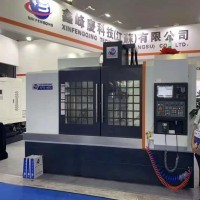
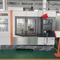
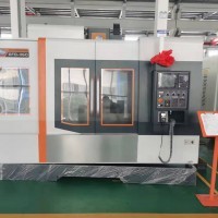
XFQ850 Vertical Machining Center
Technology Agreement
1. Equipment technical description
2. Technical parameters
3. Standard configuration
4. Main function table of the system
5. M code table
6. Installation and debugging preparation
Seven, equipment use environment requirements
8. Equipment installation and debugging
9. Equipment acceptance
10. Quality Assurance
1. Equipment technical description
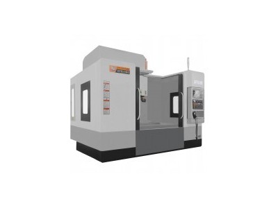
1. This equipment is a machine that can cut various parts and components, and can automatically and continuously complete various processes such as milling, drilling, boring, expanding, reaming, countersinking, and tapping. It has the characteristics of high precision, fast speed, high degree of automation, and can process complex parts of various shapes. Widely used in machining, mold, automobile and motorcycle parts, lighting, hardware, aluminum products, power tools, aerospace, military, plumbing equipment, furniture and household appliances and other industries.
2. This equipment has a square shape, mechatronics design, the center of gravity is centered and short, the base span is large, the guide rail span is wide, the non-moving parts are heavy, the moving parts are light, and the thin-wall and multi-rib structure is mostly used, which is fully enclosed. Protection, digital control, beautiful appearance.
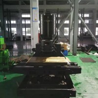
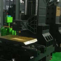
3. The fuselage is made by casting molding process. The material grade is HT300. After one tempering + natural aging treatment for more than 6 months, it is all aged in the plateau climate, with strong rigidity and not easy to deform.
4. The three axes are driven by high-precision grinding ball screws, driven by a servo motor, and the motor is directly connected with the screw, with precise positioning, fast response speed, and no backlash.
5. Linear rolling guides are used for all three axes, which can enable the machine to move accurately and quickly, and bear the force in all directions. There is no crawling during low-speed feeding, low noise, low friction resistance, and long-lasting precision. All moving parts are Automatic oil filling.
6. Standard BT40 high-speed and high-rigidity spindle, low-speed high-torque main motor, direct connection between the motor and the spindle belt, fast response speed and low vibration.
7. Equipped with 24 disc manipulator type tool magazines as standard, using high-precision and high-stability cam-type tool changing mechanism, the tool changing speed is fast; through two-way tool selection, and automatically provide the nearest path for the next tool change, Reduce non-cutting time and improve cutting efficiency.
8. Equipped with a bus-controlled full-digital high-performance, high-reliability CNC system, the products are powerful and easy to operate; this series of products are widely used in aerospace, automobile manufacturing, energy power, metal molds, and 3C industries; providing efficient, Precise motion control and process solutions.
9. Fully enclosed sheet metal protection, with automatic chip remover and tool cooling system, three observation windows are set up, and the observation windows are made of double-layer laminated rigid glass, which is convenient for viewing the internal processing status of the machine and ensuring safety.
10. All finished products undergo 48-hour full-load running-in and trial-cut processing to ensure the best positioning accuracy and servo characteristics. And the machine has undergone strict inspection measures before it is released to ensure that the precision of the machine is stable for a long time.
11. The quality of processed and assembled finished products of all machine parts conforms to product drawings and related technical requirements, its safety standards conform to the relevant provisions of GB15760-2004 "General Technical Conditions for Safety Protection of metal Cutting Machine Tools", and its accuracy standards conform to GB/T17421-2000 "General Specifications for Safety Protection of metal Cutting Machine Tools". The relevant provisions of the General Rules for Machine Tool Inspection.
2. Technical parameters
Processing range Three-axis stroke (X/Y/Z) mm800/500/500
Distance from spindle centerline to column guide surface mm550
The distance from the spindle nose to the working table is mm150~650
Maximum drilling diameter mmΦ4045# steel
Maximum tapping diameter mmM2045# steel, coarse teeth
Workbench Workbench size (length × width) mm1000 × 500
Maximum load kg400
T-slot slot width×spacing×slot number-18×90×5
Spindle Spindle diameter mmΦ150
Spindle maximum speed rpm10000 belt
Spindle taper hole - BT407: 24
Spindle taper hole runout mm0.002
Spindle motor torque N. m35.8/70 continuous/30min
Spindle motor power KW7.5/11 rated/maximum speed Rapid traverse speed (X/Y/Z)m/min48
Cutting feed rate mm/min18000
Feed motor torque N.mX, Y: 11 Z: 20Z axis with turns
Feed motor power KWX, Y: 1.8 Z: 3 rated power
The number of automatic tool changing tools is 24
Maximum tool diameter/length/weight-Φ80mm/300mm/8kg full tool
Maximum tool diameter mmΦ80/Φ150 full tool/empty adjacent tool
Tool selection method - any nearby option
Tool exchange time S1.9 tool to tool
Machine tool accuracy Positioning accuracy (X/Y/Z) mm±0.008/300
Repeat positioning accuracy (X/Y/Z) mm±0.004
Other used air pressure Mpa 0.6~0.8
Machine tool electrical capacity KVA15
Cooling box volume L120
Machine tool dimensions (length × width × height) mm2550 × 2345 × 2460
The weight of the machine is about 4800 kg
3. Standard configuration
Serial Number Name Brand/Model/Specification
1 bed Xinfengqing
2 Spindles TAIWAN 楗 Tsubaki BT40/150/10000 rpm
3 tool magazine TAIWAN Okada / Deda 24T disc tool magazine
4 ball screws X Y Z silver 4016/C3 grade
5 linear guide X-axis silver 35 balls /
6 linear guides Y-axis silver 35 balls /
7 linear guide Z-axis silver 35 balls / (4 sliders)
8 OS Mitsubishi (display 10.4")
9 Servo motor X, Y2KW m 2KW
10 Servo motor Z3KW 20N.m (with holding turn)
11 Servo drive Mitsubishi integrated amplifier
12 Spindle Motor Mitsubishi M80/10000 75-11KW 10000rpm
13 Control Appliances Schneider
14 Spindle Oil Cooler Pump Flow 3.7L/min Temperature Control Range 10-40℃
15 Pneumatic components AirTAC/Gold
4. Main function table of Mitsubishi system (some functions need to be realized in combination with the configuration of the host
No. Specifications Function Mitsubishi M80 Series Remarks
Type5
1 number of control paths 1
2 Maximum total number of controlled axes (servo axis + spindle)
3Maximum number of control servo axes
Five-axis four-linkage requires hardware support
4 Maximum number of control spindles
5 Simultaneous control of the number of axes
40 Four-axis linkage requires hardware support
6 can be connected to the servo motor
KW/αi-B , βi-B
Drilling and tapping system supports αi-B
7 Display Units 10.4" Color LCD
815" color LCD
9 Program capacity 512K (1280m)○
101M(2560m)-
11 function modules○
12PMC Ladder Diagram Command Extended Function
13PMC information display function in various languages
14 Automatic data backup
15 Memory Card Edit/Run
16 Program folder management
17AICC I high speed and high precision
18AI contour control
19 Smoothing + Tolerance Control
20 Smart Overlaps
21 intelligent front end point control
22 Servo HRV control
23 spindle HRV control
24FSSB high speed rigid tapping
25 MITSUBISHI SERVO GUIDE (Servo Wizard)
26 Memory Card/Data Server Edit and Run
27 Comprehensive operation and programming guide functions
28 programming guide function ISO code
29G code and M code help function
30 machining cycles
31 Contour programming
32 Ethernet
33 Mitsubishi program transmission U disk / network cable
34FSSB high speed rigid tapping
35 interpolation type straightness compensation
36 Intelligent Backlash Compensation
37PMC axis control (not applicable to Cs axis)
38 inclined plane indexing
39 Fast program restart
40Preparation support before processing
41 Transfer program to CF card via embedded Ethernet/USB
42Servo Guide Mate
43 Spindle Smart Load Meter
●AI contour control
Optimal speed and acceleration control based on block pre-reading enables high-speed and high-precision machining of complex free-form surfaces such as aircraft parts, automobile parts, and metal molds that are commanded with continuous micro-blocks.
●Smoothing + Tolerance Control
The appropriate processing speed is determined by commanding the allowable error (tolerance) to reduce the tedious steps and time of precision adjustment. In addition, even for continuous minute line segment commands used for machining metal molds, etc., mechanical shock can be reduced and the smoothness of the machined surface can be improved.
5. M code table (Mitsubishi M80 system)/FAN
No. M code function description No. M code function description
01M00 Program pause 07M08 Cooling water on
02M01 Choose to stop 08M09 Cooling water off
03M02 Program end 09M30 Program end
04M03 Spindle forward rotation 10M98 Call subroutine
05M04 Spindle reverse rotation 11M99 Subprogram return
06M05 Spindle stop 12
6. Installation and debugging preparation
Serial number project requirements and specification remarks
1 Factory foundation
It is confirmed that the machine tool weighs about 4800KG, covers an area of about 2.6 meters on the left and right, about 2.5 meters in the front and rear, and leaves more than 0.6 meters in the left, right, and rear directions.
The ground is firm and level, without hollow and soft conditions, add anchor bolts if necessary, and pour cement
2 Incoming power supply 60A air switch with leakage protection, three-phase 380V, voltage error less than 5%, connect 15kw voltage stabilizer if necessary, must have a ground wire access port, but no neutral wire.
3. Compressed air 0.6~0.8Mpa clean and moisture-free air source, flow rate 300L/min, trachea outer diameter ¢12 mm, the closer to the air source, the better
4. Fill the lubricating oil pump with guide rail oil or 36# clean oil
It is recommended to use No. 68 rail oil in summer and No. 32 rail oil in colder winters (especially in northern regions).
5 Installation preparation
1. Forklift, more than 5 tons, fork arm length 1.8m~2m, shift trolley, jack.
2. Crane, suitable for safe flexible slings above 10 tons.
3. Prepare 120*120*8 steel plates for uneven ground, about 10 pieces of forklift cranes can be selected from 2 or 1
6. Test machine preparation The customer prepares the blank parts to be processed, fixtures, tool holders, tools, cooling oil, etc., such as computer programming and NC program transmission, also need to prepare working computers, network cables, and professional operators.
Seven, equipment use environment requirements
7.1. The equipment maintains a constant ambient temperature, which is an essential factor for precision machining. The available ambient temperature is required to be between 5°C and 40°C, and the optimum ambient temperature is 15°C to 25°C. The air is dry and well ventilated.
7.2. Power supply voltage: 3-phase, 380V, within the range of ±5% voltage fluctuation, power supply frequency: 50HZ.
7.3. If the voltage in the area of use is unstable, the machine tool should be equipped with a regulated power supply to ensure the normal operation of the machine tool.
7.4. The machine tool should have reliable grounding: the grounding wire is copper wire, the wire diameter should not be less than 2.5mm2, and the grounding resistance should be less than 4 ohms.
7.5. In order to ensure the normal working performance of the equipment, if the compressed air of the air source does not meet the air source requirements, a set of air source purification devices (dehumidification, oil removal, and filtration) should be added before the air intake of the machine tool.
7.6. Keep the equipment away from direct sunlight, vibration sources and heat sources, as well as high-frequency generators, electric welding machines, etc., to avoid machine tool production failure or loss of machine tool accuracy.
8. Quality Assurance: The quality assurance period is 12 months from the date of receipt of the goods.


